C++ Module: spacecraftLocation
Executive Summary
This module determines if one satellite has a line of sight vector to another satellite. An oblate planet is modeled through the equatorial and the polar radius. If the line of sight vector between two satellites is above this surface, then the output access message is set to true. The module has a primary spacecraft which determines access to N other spacecraft orbiting the same planet.
Further, the module tracks a body-fixed location L on the primary spacecraft (i.e. location where an antenna is attached), and you can specify an optional sensor/communication bore sight axis \(\hat{\bf a}\) and a center-to-edge sensor/communication cone angle \(\theta\). In this case the access message is true if the line of sight vector between spacecraft is above the surface and the relative position vector to the other spacecraft is within this cone.
Lighting conditions are also considered. If a Sun message is connected and theta_solar is set, the module checks that the normal \(\hat{\bf a}\) is illuminated by the Sun with at most that incidence angle. The optional theta_view limit rejects observations made too obliquely to the normal. When a Sun message is connected, the module also reports how closely the tracked spacecraft aligns with the ideal specular reflection from the body-fixed location. This geometric glare metric can optionally prevent access so that observations with risky geometry can be scheduled for re-imaging.
Finally, if the other spacecraft is accessible, the range to the other satellite is stored in the output message.
Module Assumptions and Limitations
This module assumes all spacecraft are orbiting the same planet. The planet shape is assumed to be an ellipsoid specified through the equatorial and polar radius. To account for a planet’s atmosphere, increase these radii to account for the atmospheric height.
The glare output is a geometric specular-alignment metric. It does not model a bidirectional reflectance distribution
function, surface roughness, wavelength-dependent material properties, absolute irradiance, camera exposure, or
sensor saturation. Consequently, hasGlare indicates a user-configured risk geometry rather than proving that an
image is overexposed. Planetary eclipse geometry remains the responsibility of a separate C++ Module: eclipse module;
spacecraftLocation can consume that module’s illumination factor but does not calculate eclipse or spacecraft
self-shadowing.
Message Connection Descriptions
The following table lists all the module input and output messages. The module msg variable name is set by the user from python. The msg type contains a link to the message structure definition, while the description provides information on what this message is used for.
Msg Variable Name |
Msg Type |
Description |
|---|---|---|
planetInMsg |
(optional) planet state input message. Default is a zero state for the planet. |
|
primaryScStateInMsg |
primary spacecraft state message relative to which to evaluate access to other spacecraft in |
|
scStateInMsgs |
vector of other spacecraft state input messages. These are set through |
|
sunInMsg |
(optional) Sun state input message. Used for illumination and glare checking when connected. |
|
eclipseInMsg |
(optional) eclipse input message. Used for illumination checking if the message is connected and |
|
accessOutMsgs |
output vector of ground location access messages. |
Detailed Module Description
The spacecraftLocation module handles the following behavior:
Spacecraft body-fixed location representation: a single
spacecraftLocationinstance represents one body-fixed location on a spacecraftThe planet-centered planet-fixed frame is either a zero state (default), or read in through an optional planet ephemeris message
An optional sensor axis can be specified to ensure the primary spacecraft is pointing this axis
Computation of spacecraft visibility (i.e. access) considering range and relative field-of-view constraints
Computation of Sun incidence, tracked-spacecraft view angle, and geometric specular-glare alignment at the body-fixed location
Optional access limits on Sun incidence, spacecraft viewing angle, and specular-glare alignment
Support for multiple other spacecraft given one
spacecraftLocationinstance
Determining Line of Sight to another spacecraft
Let P be the planet-centered planet-fixed frame. The inertial planet origin is given by \({}^{N} {\bf r}_{P/N}\). The inertial position vector of the primary spacecraft B is \({}^{N}{\bf r}_{B/N}\), while the inertial position vector to the other satellite is \({}^{\cal N}{\bf r}_{S/N}\). The first step is to determine the spacecraft positions, expressed in the P frame.
The line of sight vector is defined through the point B and the direction \({\bf r}_{S/B}\). Let \(\kappa\) be a scaling factor, the line is then defined as:
The process of intersecting a line with an ellipsoid is simplified by using an affine project to render the ellipsoid a sphere. This affine mapping preserves a line to remain a line. The math of this is as follows. The planet is assumed to have rotational symmetry about the 3rd axis about which it is spinning. Thus, to map the ellipsoid into a sphere the planet relative 3rd coordinates must be scaled by the ratio of the equatorial radius to the polar radius. The following math assumes this affine mapping has been performed in the above planet-relative position coordinates.
To determine the minimum distance of the line \(\bf l\) to the planet origin, consider the cost function \(J\):
Setting the first variation of \(J\) with respect to \(\kappa\) to zero and solving for optimal \(\kappa^\ast\) yields
Note that if \(\kappa<0\) or \(\kappa>1\), then the point of closed approach is outside of the line-of-sight interval between the two spacecraft and the planet cannot be blocking access of one spacecraft from another.
Thus, the point of closed approach is determined through:
If \(|{\bf r}^\ast| > r_{\text{eq}}\) then the other spacecraft is visible relative to the primary spacecraft.
Determining Sensor Cone Inclusion
If the line of sight property is established, then the module can also take into consideration a sensor or communication boresight axis \(\hat {\bf a}\) which is fixed relative to the primary spacecraft body frame. The angle \(\phi\) between the relative position vector and this body fixed unit direction vector is found through:
The module sets the sensor cone half-angle \(\theta\). If \(\phi > \theta\) then the sensor or communication axis does not have access to the other spacecraft.
If this \(\hat{\bf a}\) is considered, then the access output message sets the message elevation angle as
Determining Solar Illumination
If the sunInMsg is connected and \(\theta_{\text{solar,max}}\) is set, the illumination of the surface is considered, treating \(\hat{\bf a}\) as the surface normal. Let \(L\) be the body-fixed location, \(H\) the Sun, and \(S\) the tracked spacecraft. The unit location-to-Sun and location-to-spacecraft vectors are
The illumination incidence condition is met if
If an eclipse message is connected and min_illumination_factor is set, the module will also check that the
illumination factor is above this threshold. The eclipse factor is supplied by a separate C++ Module: eclipse model so
eclipse geometry is not duplicated here. Spacecraft self-shadowing is not modeled.
Determining the Viewing Angle
The surface-normal-to-observer angle is
It is reported as scViewAngle whenever aHat_B is configured and a tracked spacecraft is connected; no Sun
message is needed. Setting theta_view to a nonnegative maximum rejects access when
\(\theta_{\text{view}} > \theta_{\text{view,max}}\). The default negative value disables this requirement.
This is an observation-obliquity check, distinct from the sensor cone angle theta and from the angle
\(\delta\) between the ideal reflected ray and the viewing direction.
Determining Specular Glare
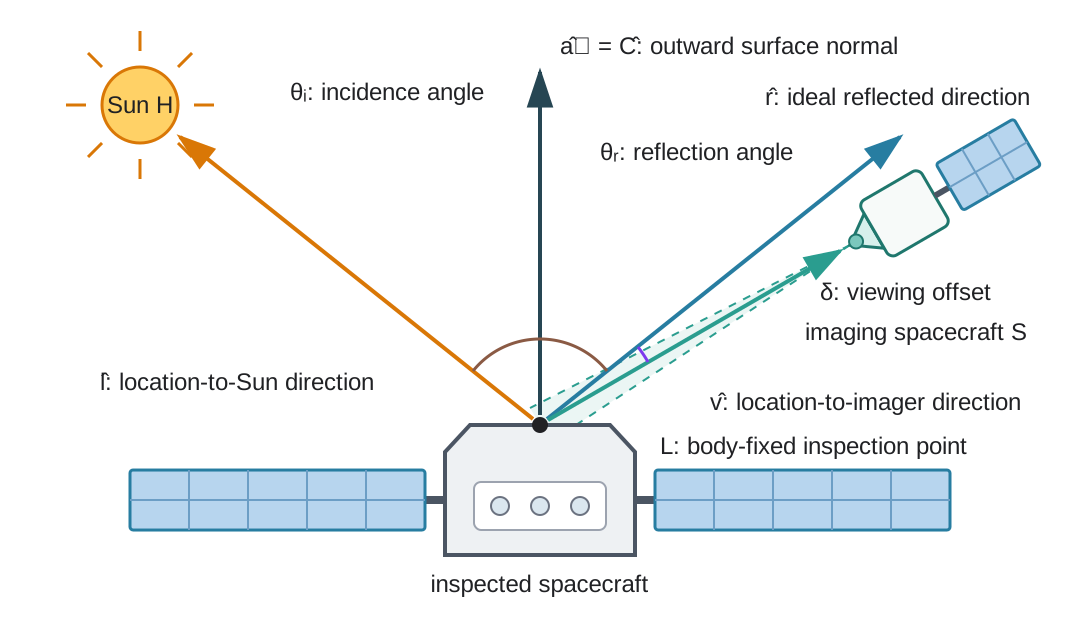
Specular-glare geometry at the body-fixed surface point \(L\). The two-dimensional drawing shows the ideal coplanar case; the vector calculation is performed in three dimensions. The ideal reflection has equal incidence and reflection angles, while the offset \(\delta\) between \(\hat{\bf r}\) and \(\hat{\bf v}\) controls the reported glare factor.
For an illuminated, front-facing surface, the ideal outgoing reflection of incoming sunlight is
The reflected-ray viewing offset shown in the figure is
The module defines the dimensionless geometric glare factor as
with \(g=0\) when either the Sun or tracked spacecraft is behind the surface. Back-facing geometry is never
classified as glare, even when glareThreshold is zero. The value is clamped to \([0,1]\), and \(g=1\) is
exact alignment with the specular reflection. This single alignment test captures both equal incidence/view angles
and coplanarity, including the normal-incidence case where cross-product-based plane normals are undefined.
The peak of this geometric alignment coincides with the specular peak of the Blinn–Phong model used by van Wijk et al.. The module does not evaluate that model’s intensity profile: material coefficients, a shininess exponent, light intensity, and sensor-dependent thresholds would be needed for radiometric overexposure predictions.
The output hasGlare uses an inclusive comparison against glareThreshold, with an absolute tolerance of
16 times double-precision machine epsilon to accommodate numerical roundoff. This includes exact reflections
when glareThreshold is 1. The reported glareFactor retains the computed, clamped alignment.
The default glareThreshold is 0.95. It must be finite and in [0, 1]; invalid values raise an error during
initialization. Glare is evaluated separately for every spacecraft connected through
addSpacecraftToModel() and only when sunInMsg
is connected. If no surface normal is supplied through aHat_B, both glare outputs remain zero. By default, glare
is reported without modifying access. Setting useGlareConstraint to True also clears hasAccess for glared
observations, allowing an inspection planner to leave those points available for re-imaging.
User Guide
A new instance of spacecraftLocation, alongside necessary user-supplied parameters, can be created by calling:
location = spacecraftLocation.SpacecraftLocation()
location.ModelTag = "scLocation"
location.rEquator = orbitalMotion.REQ_EARTH * 1000.
location.rPolar = orbitalMotion.RP_EARTH * 1000.  # optional, include to account for oblateness
location.maximumRange = 100e3 # optional, sets maximum range for visibility in meters
scSim.AddModelToTask(simTaskName, location)
The variable maximumRange is optional and set to -1 by default. If it is set to a positive value, then the hasAccess variable is only set to 1 if the relative spacecraft distance is less than this maximum range.
An optional planet ephemeris is connected via the planetInMsg input message:
location.planetInMsg.subscribeTo(planetMsg)
If this message is not connected, then zero planet position and attitude orientation are set.
To set a primary spacecraft body fixed sensor or communication axis \(\hat{\bf a}\) and half-cone angle \(\theta\), use:
module.aHat_B = [xxx, xxx, xxx]
module.theta = xxx * macros.D2R
For a surface inspection point, configure the body-fixed point location and outward normal, connect the Sun, and optionally reject glared views:
location.r_LB_B = [xPoint, yPoint, zPoint]  # [m]
location.aHat_B = [cHatX, cHatY, cHatZ]  # [-]
location.theta = 90.0 * macros.D2R  # [rad]
location.theta_solar = 90.0 * macros.D2R  # [rad]
location.theta_view = 75.0 * macros.D2R  # [rad], optional viewing-obliquity limit
location.glareThreshold = 0.95  # [-]
location.useGlareConstraint = True
location.sunInMsg.subscribeTo(sunMsg)
The output glareFactor can be retained as an observation-quality feature even when useGlareConstraint is False. For a point-cloud RSO model, create one module instance per body-fixed point and connect each instance to the same Sun and imaging-spacecraft state messages.
Spacecraft can be added to the model by calling:
location.addSpacecraftToModel(sc1.scStateOutMsg)
location.addSpacecraftToModel(sc2.scStateOutMsg)
The access output messages can be logged through:
dataRec0 = location.accessOutMsgs[0].recorder()
dataRec1 = location.accessOutMsgs[1].recorder()
Warning
min_shadow_factor is deprecated in favor of min_illumination_factor.
In C/C++ both names work until Dec 31, 2026. After that date, code must
use min_illumination_factor exclusively.
-
class SpacecraftLocation : public SysModel
- #include <spacecraftLocation.h>
ground location class
Public Functions
-
SpacecraftLocation()
Creates an instance of the SpacecraftLocation class.
-
~SpacecraftLocation()
Empty destructor method.
-
void UpdateState(uint64_t CurrentSimNanos)
update module
- Parameters:
CurrentSimNanos –
-
void Reset(uint64_t CurrentSimNanos)
Resets the internal position to the specified initial position.
-
bool ReadMessages()
Read module messages
-
void WriteMessages(uint64_t CurrentClock)
write module messages
-
void addSpacecraftToModel(Message<SCStatesMsgPayload> *tmpScMsg)
Adds a scState message name to the vector of names to be subscribed to. Also creates a corresponding access message output name.
Public Members
-
double rEquator
[m] equatorial planet radius
-
double rPolar
[m] polar planet radius
-
double maximumRange
[m] Maximum slant range to compute access for; defaults to -1, which represents no maximum range.
-
Eigen::Vector3d aHat_B
[] (optional) unit direction vector of the sensor/communication boresight axis
-
double theta
[r] (optional) sensor/communication half-cone angle, must be set if shat_B is specified
-
double theta_solar
[r] (optional) illumination half-cone angle, treating aHat_B as the surface normal
-
double theta_view
[rad] (optional) maximum angle from the surface normal to the tracked spacecraft
-
double min_illumination_factor
[] (optional) minimum amount of illumination due to eclipse necessary to observe
-
double min_shadow_factor
[] (DEPRECATED) Alias for min_illumination_factor. Use min_illumination_factor instead.
-
double glareThreshold
[-] minimum specular alignment classified as glare; defaults to 0.95
-
bool useGlareConstraint
[-] if true, detected glare prevents access; defaults to false
-
ReadFunctor<SCStatesMsgPayload> primaryScStateInMsg
primary spacecraft input message
-
ReadFunctor<SpicePlanetStateMsgPayload> planetInMsg
(optional) planet state input message
-
ReadFunctor<SpicePlanetStateMsgPayload> sunInMsg
(optional) sun data input message
-
ReadFunctor<EclipseMsgPayload> eclipseInMsg
(optional) eclipse input message
-
std::vector<Message<AccessMsgPayload>*> accessOutMsgs
vector of ground location access messages
-
std::vector<ReadFunctor<SCStatesMsgPayload>> scStateInMsgs
vector of other sc state input messages
-
Eigen::Vector3d r_LB_B
[m] position of the location relative to the spacecraft frame origin B, in B frame components
-
BSKLogger bskLogger
— BSK Logging
Private Functions
-
void computeAccess()
compute the spacecraft to spacecraft access messages
Private Members
-
std::vector<AccessMsgPayload> accessMsgBuffer
buffer of access output data
-
std::vector<SCStatesMsgPayload> scStatesBuffer
buffer of other spacecraft states
-
SCStatesMsgPayload primaryScStatesBuffer
buffer of primary spacecraft states
-
SpicePlanetStateMsgPayload planetState
buffer of planet data
-
SpicePlanetStateMsgPayload sunData
buffer of sun data
-
EclipseMsgPayload eclipseInMsgData
buffer of eclipse data
-
Eigen::Matrix3d dcm_PN
Rotation matrix from inertial frame N to planet-centered to planet-fixed frame P.
-
double zScale
ration of rEquator over rPolar, used for affine scaling to turn ellipsoid to sphere
-
std::vector<std::unique_ptr<Message<AccessMsgPayload>>> ownedAccessOutMsgs
Storage for accessOutMsgs.
-
SpacecraftLocation()